Manufacturing / CAD assembly drawings
Rotary welding-table assembly
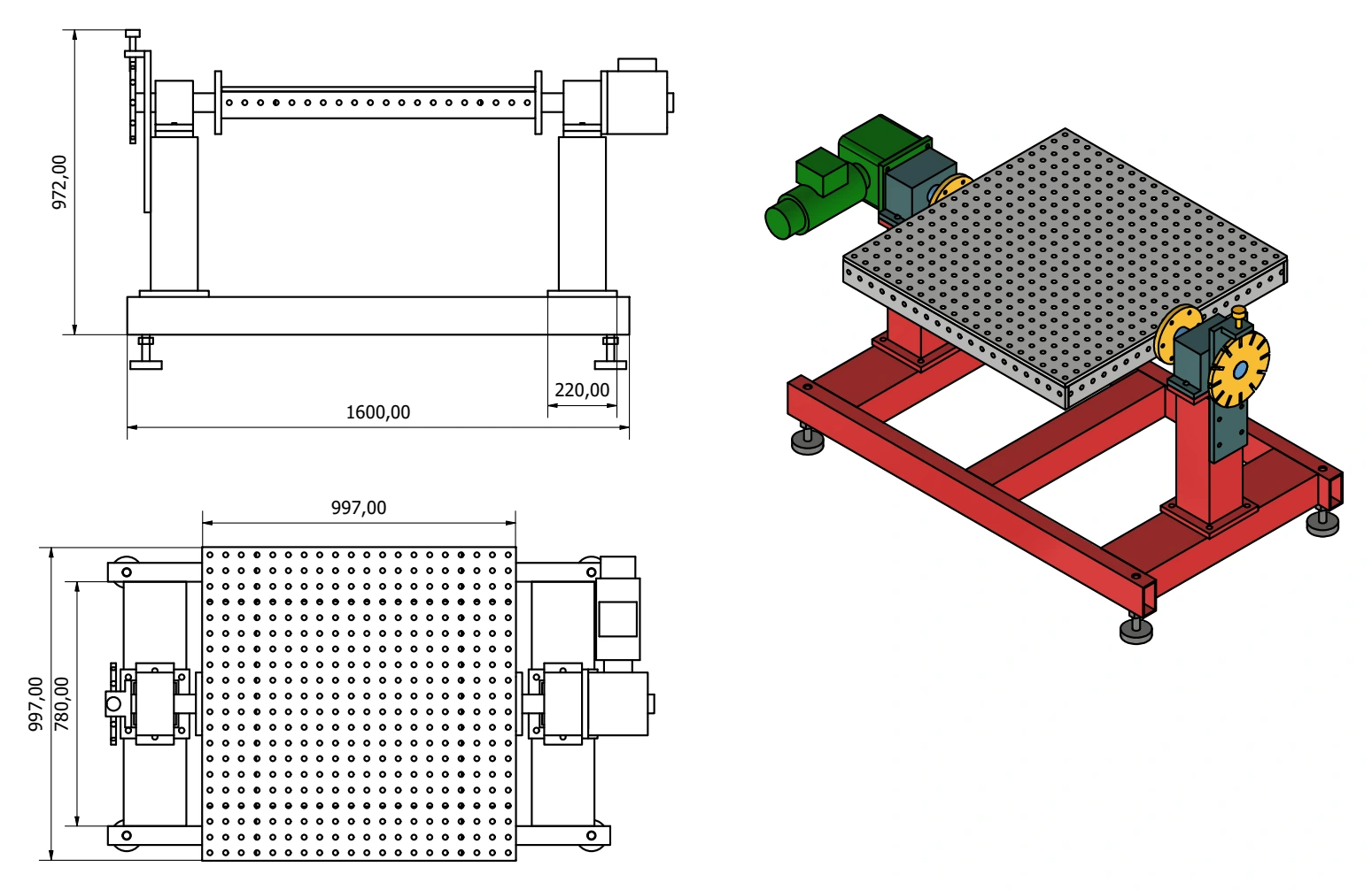
A compact rotary welding-table assembly with a perforated worktop mounted between two support columns. The sheet pairs dimensioned 2D views with a coloured 3D view of the frame, drive and indexing arrangement.
Discuss a similar project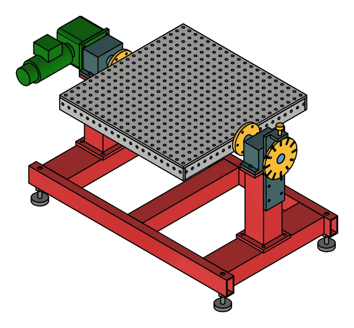
Drawing scope
From 3D arrangement to dimensioned assembly.
The elevation sets out the table height and base arrangement. The plan view shows the worktop pattern and the position of the supporting and drive components. The isometric view adds a clear picture of how the perforated plate, frame and rotating supports fit together.
What the assembly drawing shows
- An elevation defining the overall height and base dimensions.
- A plan view documenting the worktop footprint and assembly layout.
- A coloured isometric assembly showing the support columns, base frame, levelling feet and drive arrangement.
Showing both orthographic and isometric views helps a project team review an assembly before developing its fabrication details. This portfolio example demonstrates the drawing arrangement; it does not establish production status, load capacity or completed manufacture.
SolidCAD supports manufacturers and fabricators with CAD drafting, assembly documentation and shop drawings from Dandenong, Victoria, for projects across Australia.
Assembly drawing views
Elevation, plan and isometric drawing extracts. Title blocks and personal identifiers have been cropped out.
 View enlarged assembly drawing