Manufacturing / CAD assembly drawings
Motorised welding-table assembly
A rectangular welding-table assembly combining a perforated worktop, a fabricated base frame and a geared drive. The drawing brings the overall arrangement and component relationships into one coordinated sheet.
Discuss a similar project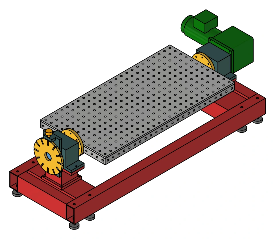
Drawing scope
From 3D arrangement to dimensioned assembly.
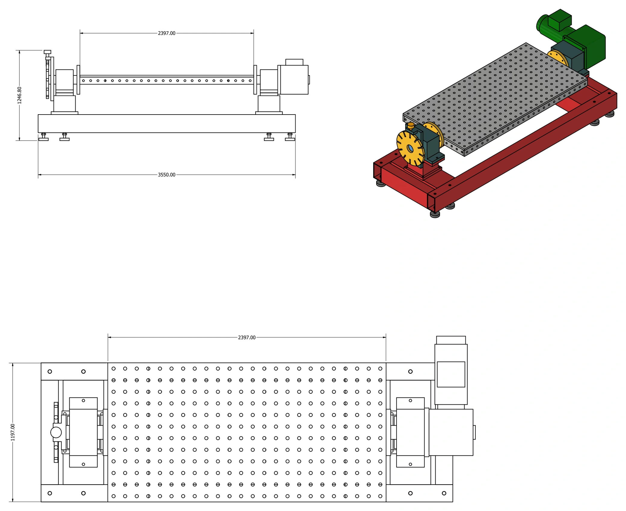
The elevation shows the relationship between the worktop, supporting columns and base frame, while the plan view sets out the perforated surface and the drive position. A coloured isometric view makes the assembly easier to understand alongside the dimensioned 2D views.
What the assembly drawing shows
- Dimensioned elevation and plan views of the complete assembly.
- A 3D isometric view showing the worktop, frame, columns and geared drive.
- A parts list in the source sheet identifies the worktop, ribs, trunnion shafts, bearing housings, columns, base-frame members, levelling feet and drive components.
This example shows how mechanical CAD drafting can connect assembly geometry with a component schedule. The drawing extracts focus on the arrangement; individual manufacturing details, tolerances and fabrication instructions belong in the wider drawing package.
SolidCAD supports manufacturers and fabricators with CAD drafting, assembly documentation and shop drawings from Dandenong, Victoria, for projects across Australia.
Assembly drawing views
Elevation, plan and isometric drawing extracts. Title blocks and personal identifiers have been cropped out.
 View enlarged assembly drawing