Shop drawings / Actual drawing example
Aluminium bar balustrade shop drawings.
A ten-sheet shop drawing package for an aluminium balustrade with a perforated bar top and a flat-bar shelf, issued at Revision B. Four anonymised extracts are shown here, from the 3D overview to the shelf splice.
Discuss your balustrade drawing requirements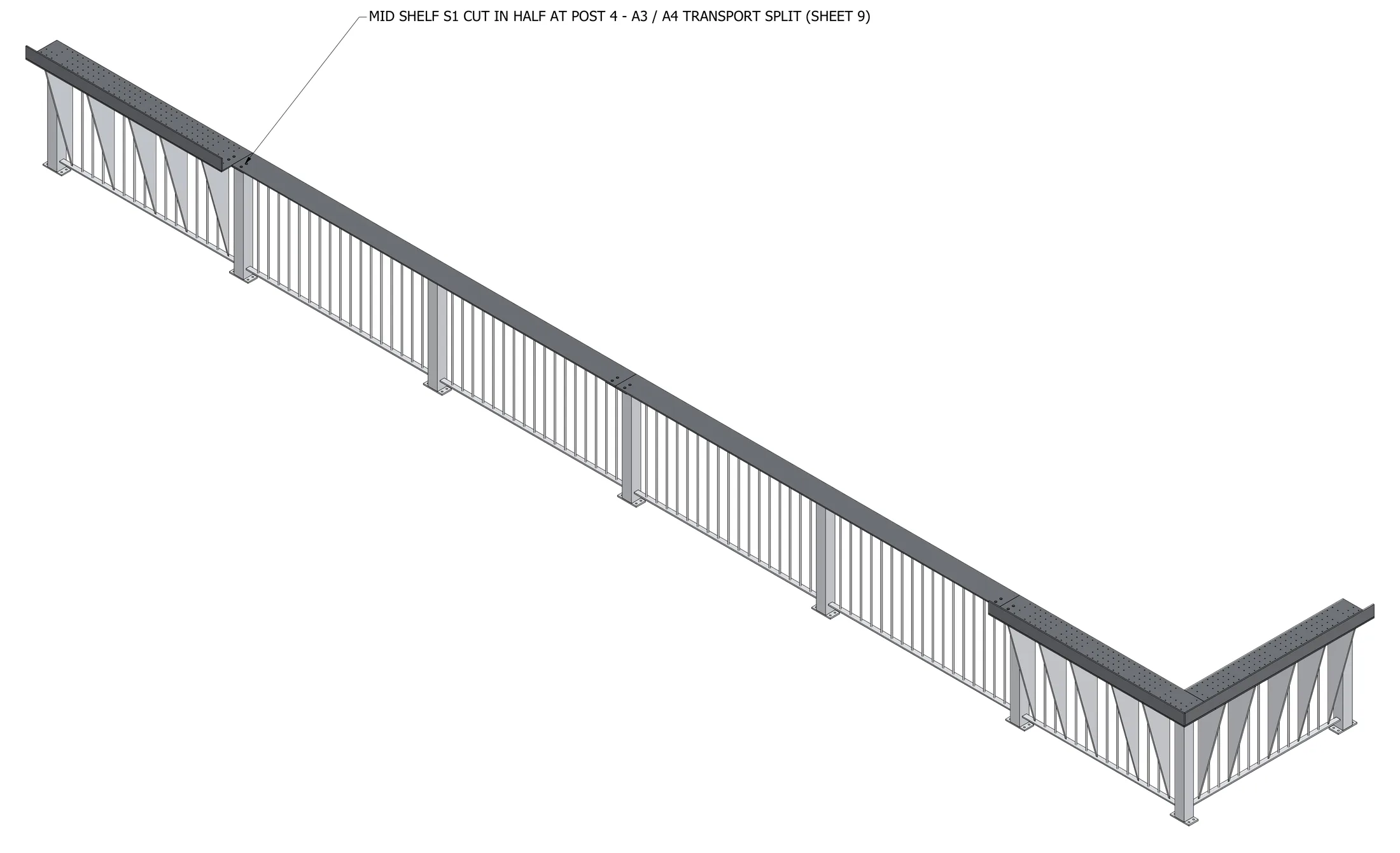
Drawing scope
From the 3D model to workshop assemblies.
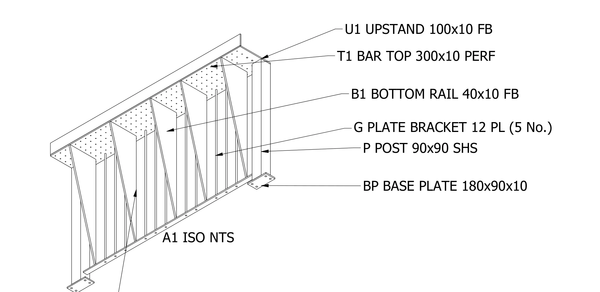
The balustrade uses 90 x 90 SHS posts on base plates, 12 mm rod infill and a 40 x 10 flat-bar bottom rail. The bar sections carry a 300 mm perforated bar top with an upstand, supported by triangular plate brackets in line with the rods, and the middle bays carry a 200 x 10 flat-bar shelf.
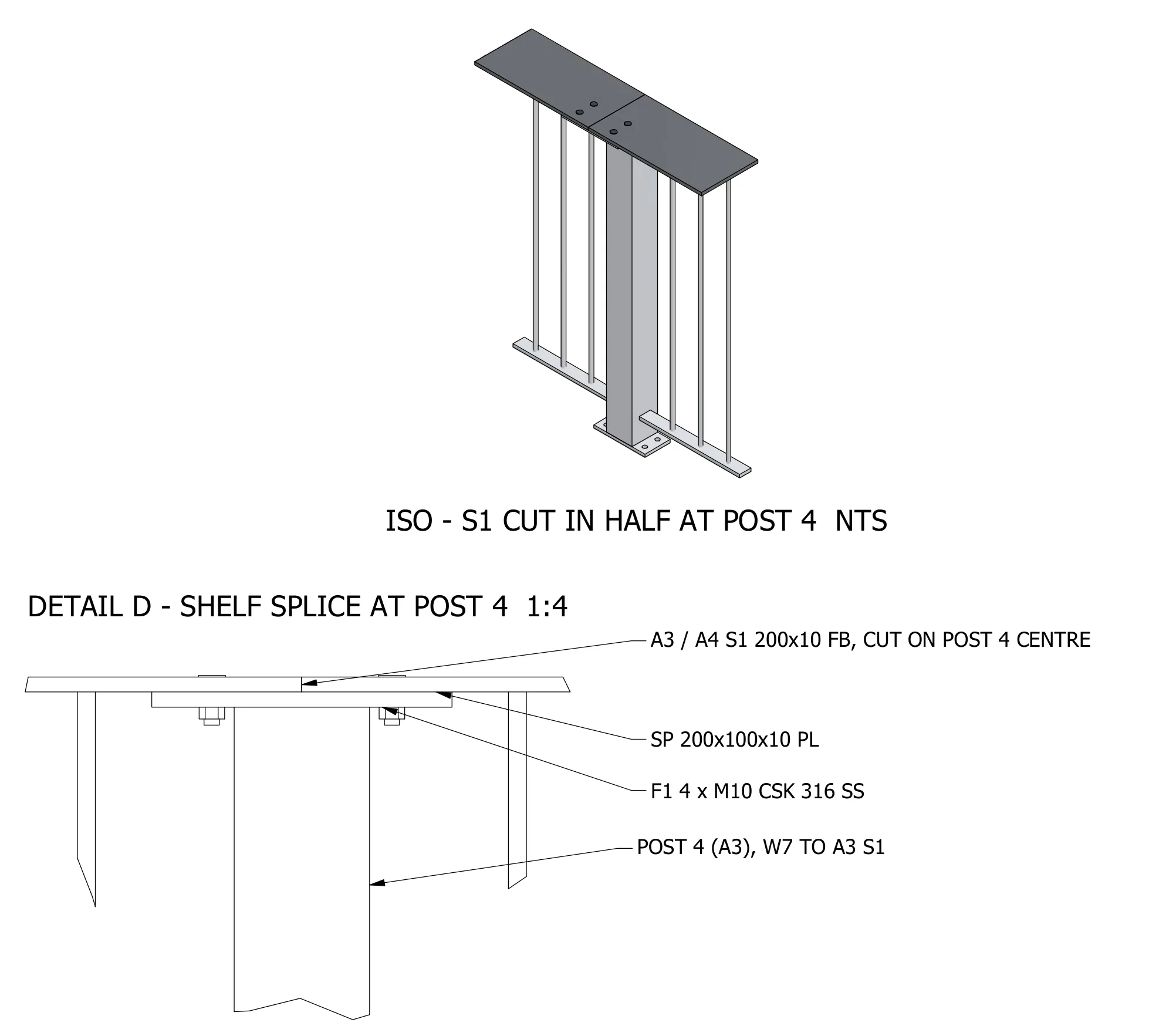
To suit transport, the run is split into four shop assemblies. The middle shelf is cut at one post and joined on site with a bolted splice plate, using stainless steel bolts with nylon isolating washers against the aluminium. The package includes setout and rod-position tables, assembly and part drawings, a bill of materials with cut lengths, a weld schedule and the splice details.
What these extracts demonstrate
- A 3D overview showing how the shop units fit together.
- Assembly drawings with a part mark on every component.
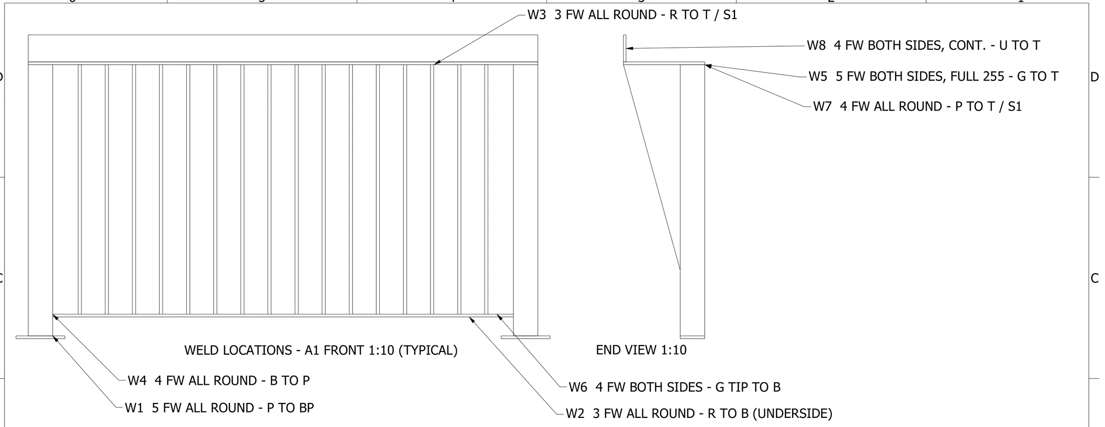
- Weld locations and a weld schedule for the workshop.
- Hold points clouded so open items are confirmed before fabrication.
Client and site details and the title blocks have been removed, and the original PDF is not offered for download. Weld sizes and fixings shown were proposed for the engineer to confirm.
Briefing a similar balustrade project
Share the architectural drawings or a sketch, the material, the rail and infill type, fixing details and any transport limits. SolidCAD can review the scope and prepare a tailored quotation.
3D overview of the balustrade
View enlarged drawingBar unit assembly with part marks
 View enlarged drawing
Weld locations
 View enlarged drawing
Shelf splice for transport
 View enlarged drawing